Bench tool
Cathode Bypass Cap Calculator
Find the -3dB corner where a cathode bypass cap stops fully bypassing the cathode resistor — the point where a gain stage's low end starts to "bloom" and gain starts dropping toward the unbypassed value.
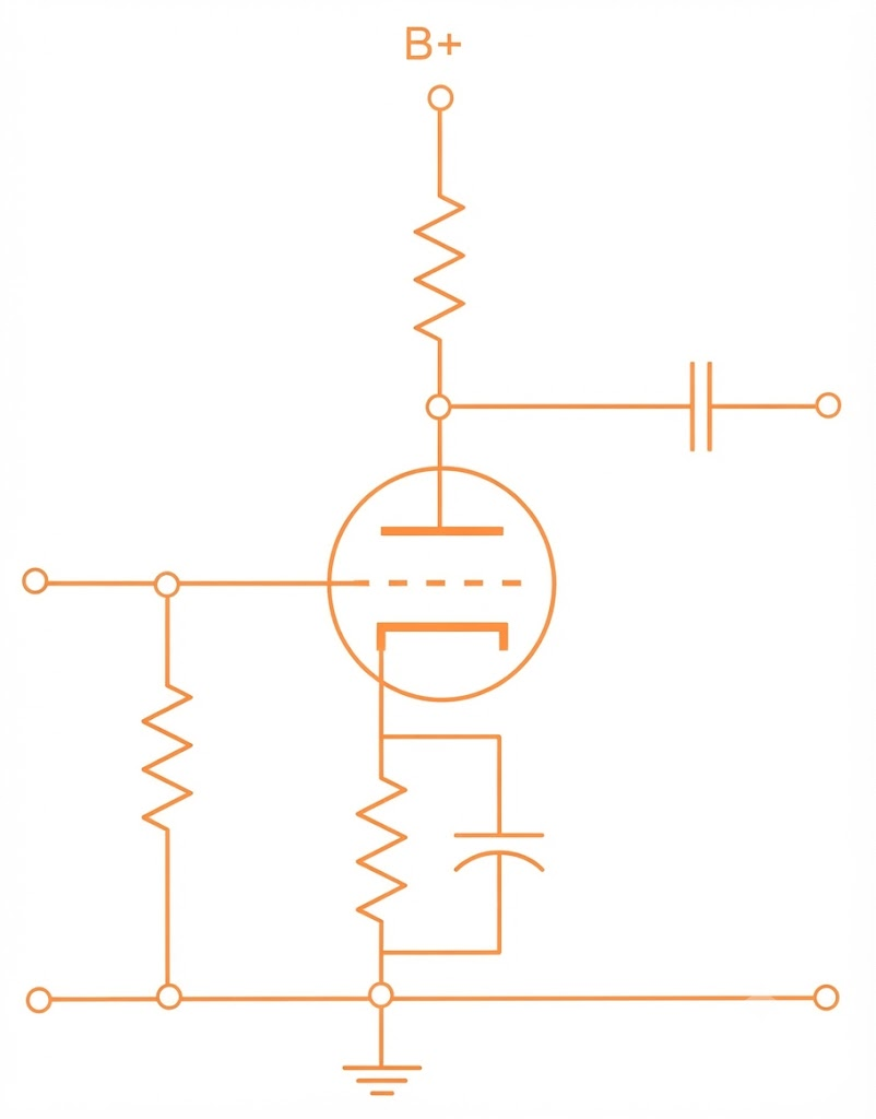 Ra
Ck
Rk
Ra
Ck
Rk
Find Corner Frequency
Enter the stage's component values and the tube's operating parameters — get back the actual -3dB point, which sits higher than a plain Rk×Ck estimate because of the tube's own gain.
Size Cap for Target Frequency
Same circuit, solved the other way — pick the corner frequency you want and get the capacitor value.
The bypass cap sees the cathode resistor Rk in parallel with the tube's own dynamic cathode resistance, (Ra + rp) / (mu + 1) — not just Rk alone. That extra term is usually smaller than Rk, which is why real corner frequencies run higher than a naive 1/(2πRkCk) estimate. rp shifts with the actual operating point (plate voltage and current), so treat the tube-preset values as a starting point and substitute your datasheet or measured figure for precision.
Common practice: a corner well below 20 Hz (5–15 Hz) keeps the stage fully bypassed across the audible band. Deliberately raising the corner into the 50–200 Hz range is a known way to thin out and tighten low end in a specific gain stage — some classic designs use a small cathode cap for exactly that reason.